Extracting Optical Marks
In this guide, you’ll learn how to extract optical marks from a document.
We’ll assume you’ve already scanned your filled forms and stored their identifiers in an array of integers called filledForms.
OMR Processing
For each scanned filled document in filledForms, we need to measure the difference in the position between the anchor in the filled form and the original anchor position in the template. Then, we need to apply the same difference to each OMR rectangle and send those rectangles for recognition.
Anchoring
After creating an anchor template called anchorTemplate, we can now search for that anchor in every filled document.
To find an anchor in a document, provide the following to the FindAnchor function:
-
The document you’re searching in
-
An anchor template
-
Search mode, and whether speed or accuracy is preferred
-
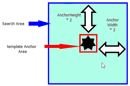
The search area
Please note that the bigger the search area is, the more time it’ll take the function to execute.
In the following code, the search area is five times each dimension of the original anchor:
// Parameters for the new location of the anchor.
int NewLeft = 0;
int NewTop = 0;
int NewWidth = 0;
int NewHeight = 0;

// Accuracy of the recognition process.
double Accuracy = 0;

// Calculating the width of the original anchor. divided by 2.
int doubleWidth = anchorWidth / 2;
// Calculating the height of the original anchor, divided by 2.
int doubleHeight = anchorHeight / 2;
// Finding the anchor.
oGdPictureImaging.FindAnchor(filledForm, anchorTemplate, OMRMode.FavorSpeed, anchorLeft - doubleWidth, anchorTop - doubleHeight,
      anchorWidth + doubleWidth, anchorHeight + doubleHeight, ref NewLeft, ref NewTop, ref NewWidth, ref NewHeight, re
In the code above, filledForm refers to the GdPictureImage identifier of the current filledForms index. It’s assumed that you loop through your filledForms array and get it.
The doubleWidth and doubleHeight parameters are calculated to enlarge the search area from the area of the original anchor template to 25 times that area. This is done by padding both amounts to each of the four parameters of the search rectangle.
What’s above is a suggestion, and the values you use can and may vary, depending upon the type of anchor and the scanning process.
Please note that the larger the search area is, the slower the algorithm will run, and the smaller the search area is, the faster the algorithm will run.
Measuring Translation
Once we’ve located the position of the anchor in the filled document, we can compare it to the location of the anchor in the template.
For example, assume the position of the template anchor in the template was in pixels at (50, 50), and that it was found in the filled form at position (55, 48).
The X translation would be 5 pixels, and the Y translation would be -2 pixels.
The code below shows how to calculate the translation once you have the location of the template anchor and the filled form anchor:
int xDifference = NewLeft - anchorLeft;
int yDifference = NewTop – anchorTop;
Applying Translations to OMR Rectangles
The code below shows how to apply a translation by making a copy of the original omrRECT array and moving the X and Y locations by the translations measured in the previous step:
Rectangle[] filledRECT = new Rectangle[8];

for (int i = 0; i <= 7; i++)
{
   filledRECT[i].X = omrRECT[i].X + xDifference;
   filledRECT[i].Y = omrRECT[i].Y + yDifference;
   filledRECT[i].Width = omrRECT[i].Width;
   filledRECT[i].Height = omrRECT[i].Height;
}
Now you have eight rectangles in an array called filledRECT, and they correspond to the locations of the OMR fields in the current filled document.
Optical Mark Detection
Now it’s time to get the results of our OMR fields in the filled document. We do this by calling one of the OMR detection functions with the appropriate overload.
Categories of OMR Detection Functions
OMR detection functions are split into two categories, depending on the shape of the OMR field:
-
Square and circular
-
Oval
While it might seem that oval and circular OMR fields should be grouped together, the “closeness” of the X and Y axis dimensions makes circular fields more similar to square fields than to oval fields.
Each of those two groups has many overloads that do the following:
-
Automatic detection without the need for any other specifications (recommended in most cases).
-
Detection based on a parameter that specifies whether or not the OMR fields contain characters.
-
Detection based on a sensitivity parameter that controls how much “filling” each field needs to have to be counted as filled or not. It also returns an array that corresponds to each field result’s confidence.
For more information on all the overloads, please refer to the API reference pages on OMRDetectMarks and OMRDetectOvalMarks.
How to Obtain Results via an OMR Detection Function
This section shows how to create an array of integers for storing the results of the detection process.
Each index in the array corresponds to the result rectangle of the same index in the array of rectangle, filledRECT, that was supplied to the OMR detection function:
int[] Result = new int[8];
// Call the OMR detection function.
// Automatic detection.
// Eight OMR fields.
// Each field as a character inside of it.
Result = oGdPictureImaging.OMRDetectOvalMarks(filledForm, filledRECT, 8, true);
Now you should have the results of all eight OMR fields.
For example, Result[3] corresponds to the result of the fourth OMR field — in other words, to the OMR field that has the location filledRECT[3].
If Result[3] = 0, then the fourth OMR field wasn’t filled. Conversely, if Result[3] = 1, then the fourth OMR field was filled.
Conclusion
The OMR process, while daunting at first, is logical once you understand all the components.
This guide is merely a simple example that can be expanded upon, depending on your preference and/or your system requirements.